
|
|
|
|
Главная --> Промиздат --> Map principle 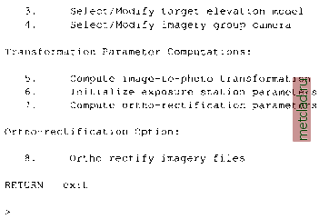 We will use all menu items sequentially, except for menu item (6) which is required only for oblique aerial images (see Section 10.3.3) or for GPS-equipped flights. It is possible to interrupt the procedure between the steps and continue later; i.ortho.photo will store all settings. 1. Select/Modify imagery group. You have already completed this task when starting the module when you had to select a group. Check on top of the menu in the terminal window whether the appropriate image group is selected. If necessary, you can switch to another image group. 2. Select/Modify imagery group target. As a next step, the target LOCATION has to be selected. Enter the name of the projected LOCATION and MAPSET. This menu item corresponds to the module i.target (as discussed earlier in Section 9.4.1). For Spearfish enter spearfish as TARGET LOCATION and your name as MAPSET (if that MAPSET does not exist, you can use userl). To see a list of existing LOCATIONS or MAPSETs enter list into the related line. 3. Select/Modify target elevation model. Specify the name of the DEM which is stored in the target LOCATION. For Spearfish enter elevation.dem or the recently interpolated elevation model at a higher resolution. 4. Select/Modify imagery group camera. We will now define camera specific parameters. If you previously defined a camera within this MAPSET, you can load it. For our example, we enter the new name gscamera. Then the following screen appears: 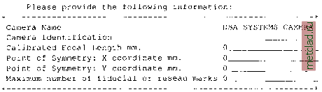 We enter the following parameters which belong to the photo gs13.l (in MAPSET userl you can find the camera parameters file gscam which belongs to the aerial photos gs13.1 and gs14.1): Please provide the following information: Camera Name Camera Identification Calibrated Focal Length mm. Point of Symmetry: X-coordinate mm. Point of Symmetry: Y-coordinate mm. Maximum number of fiducial or reseau marks gscam gs-vqcy 152 . 41 Important parameters are the Calibrated Focal Length which is usually printed on the aerial photo (or delivered along with the aerial photo in a calibration report, for explanation see Section 10.1). The calibrated focal length is unique for each camera. In our example, the gscam focal length is 152.41 mm. The coordinates of the Point of Symmetry are kept zero since it is the origin for the image coordinates. If the camera data sheet provides different values for the Point of Symmetry than the ones provided by the manufacturer, they have to be specified. The number of fiducial marks can be seen on the aerial photo or taken from the photo accompanying camera description file. Four and eight fiducial marks are common. After leaving this screen by <ESC><ENTER> the screen for definition of the distances of the fiducial maps appears. These distances are referring to the Point of Symmetry. The distance of the bright point inside the fiducial marks with respect to the point of symmetry has to be entered. The fiducial marks may be numbered as desired, but once defined, the numbering sequence must be kept identical to avoid reference errors from assignments of coordinates. If the calibration report defines the order, it should be used. Examples of photos with four or eight fiducial marks are given in Figure 10.4. In a perfect 23 cm * 23 cm (9 * 9 ) aerial photo, the distance of the bright points is 113 mm from the point of symmetry. The distances depend on the camera type and will be provided by the camera manufacturer. According to the coordinate system, with its point of origin being set to the image center, we define the following values for the gs13.1 aerial photo (all values are in millimeters). You may start with the upper left fiducial mark (no. 1), the other marks are numbered clockwise, until we reach the middle fiducial mark on the left side (no. 8, compare Fig 10.4). The coordinates are entered accordingly: 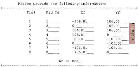 Now all required camera data are entered and we can go back to the main menu. 5. Compute image-to-photo transformation. Now we will establish the interior orientation of the image, which describes the relation between the physical extent of the aerial diapositive (in millimeters) and its pixels. The coordinate system is centered between the fiducial maps on the photo. The fiducial marks coordinates (as listed in the above table) are assigned to the fiducial marks in the image. This is done graphically in the GRASS monitor 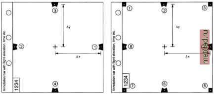 Figure 10.4. Fiducial marks in aerial photo. Left a variant with four fiducial marks, right a variant with 8 fiducial marks. The contents of annotation bar depend on the camera type
|