
|
|
|
|
Главная --> Промиздат --> Map principle transformation of the central projection of the photo to an orthogonal projection including the correction of elevation-induced scale changes; if needed, orientation of the aerial photo towards north (rotation by 90° or 270°), because imaging flights are mostly done in either east-west or west-east direction, to minimize sun illumination effects. 10.3.1 Aerial photo and LOCATIONS preparation If the aerial photo is available only on an analog medium, the diapositive, it needs to be scanned using a (photogrammetric) backlight scanner. To change a standard flatbed scanner to a backlight scanner a special device is necessary. High quality is important to avoid the introduction of internal image distortions. The scan resolution during the scanning process determines the effective ground resolution. The required value for the scan software can be calculated from the averaged image scale (see above Equation 10.1). The scanning resolution is usually specified in dpi (dots per inch). The ground resolution Rg in relation to the photo map scale is derived from the scale number M and the scanning resolution (first considered in centimeter) as follows: Rg[cm] = (10.3) Rs[lines / cm] For example, we have an aerial photo with the average scale 1:10,000. The scale number is M = 10,000 cm accordingly. The desired spatial resolution on ground Rg for the aerial photo is 40 cm (raster cell width and length). After rearranging the Equation 10.3, the scan resolution Rs which has to be defined for the scanner software is calculated as: 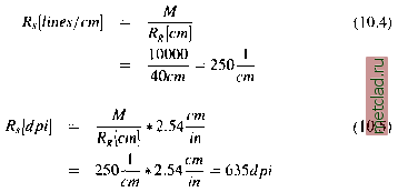 In our example, the scan resolution has to be set to 635 dpi to obtain an average ground resolution of 40 cm. It is important to know that a certain pixel resolution does not allow to recognize objects of the same size. An object always needs to be covered by several pixels to become recognizable. Another decision has to be made about the desired color depth, e.g. whether 256 or more colors should be used. The amount of required disk space is increased accordingly; a standard aerial photo scanned at 1200 dpi with 24 bit color depth will need more than 300 MB per image. Once the scan procedure is done, an image processing software (e.g. gimp) should be used to ensure that the bright fiducial marks within the fiducial marks are well visible. A zoomed fiducial mark is shown in Figure 10.3. These marks are crucial for the image-rectification task. This test of visibility can be used to define the lowest acceptable scan resolution. While verifying the fiducial marks, it is useful to zoom-in and denote the parameters from the photos annotation bar: aircraft altitude, (calibrated) focal length and the timestamp. Generation of the georeferenced target LOCATION. In the process of or-thophoto generation, the scanned and imported aerial photo is ortho-rectified into a georeferenced LOCATION. This LOCATION, containing the reference map and the DEM, has to be created first. The default resolution should be defined in respect to the final target ground resolution of the aerial photo(s). Further details about defining a LOCATION are given in Section 3.2. As mentioned above, it may be necessary to interpolate the DEM to a higher resolution, as shown in Section 5.3.4, in order to minimize unwanted displacements due to DEM resolution problems. Before leaving the projected LOCATION it is recommended to adjust the settings such as resolution and current region to the desired resolution and coordinates to enable GRASS to store the orthophoto accordingly. 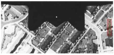 Figure 10.3. Zoomed fiducial mark in an aerial photo. The center of the bright point within the fiducial mark is used during the ortho-rectification process 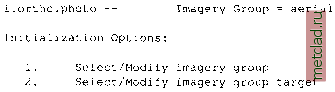 Creation of the xy LOCATION for the scanned aerial photo. You need to restart GRASS to generate the xy LOCATION for the scanned aerial photo(s). Multiple aerial photos can be imported into the same xy LOCATION. Be sure to define the LOCATION large enough to hold the image(s). When importing photos with r.in.gdal, this module optionally extends the current region if needed (flag -e). The resolution is set to one pixel. Then you need to create a separate image group for each aerial photo (see Section 9.3.2). Only in case of multi-channel aerial photos you will add all channels in one group. For our example, the xy LOCATION imagery is already available on the GRASS Web site which we will use in this chapter. 10.3.2 Orthophoto generation from vertical aerial photos The examples provided in this subsection are based on the aerial photos available in the Imagery LOCATION. We will ortho-rectify the photo gs13.1 into the Spearfish LOCATION and also give additional tips for processing your own data. For our example, the gs13.1 photo, it is important to have an appropriate high resolution elevation model available in the Spearfish LOCATION. To create it from the existing map elevation.dem, you may restart GRASS with this LOCATION, zoom into Spearfish city (located north-west in the Spearfish region) and set the raster resolution to 1m. Now interpolate the elevation model elevation.dem to the new resolution within the current region. Start the generation of orthophoto by restarting GRASS and entering the demo xy LOCATION imagery with your name as MAPSET. Then generate an image group aerial with i.group and select the photo gs13.1 as member: i.group group=aerial in=gsl3.1 The GRASS orthophoto module incorporates several photogrammetric tools. After opening a GRASS monitor, it starts with: i.ortho.photo If you have already generated the group aerial, it will be automatically loaded. Otherwise, enter the previously created image group containing the aerial photo. Then you reach the main menu:
|