
|
|
|
|
Главная --> Промиздат --> Map principle marks through lines, it is the point where these lines intersect. For oblique photos the nadir is offset from the principal point, the angle between the two being called the nadir-distance (see Figure 10.1). In such case the nadir can be derived by connecting the alignments of vertical objects such as trees or buildings. A vertical aerial photo is in central projection. This projection can also be assumed for the above mentioned slightly tilted vertical photos. There are significant differences between an aerial photo and a map (which is in orthogonal projection). Because of central projection aerial photos are free from displacements only in the nadir. Displacements increase from the nadir towards the image edges (Hildebrandt, 1996:151), which requires ortho-rectification. These displacements are intensified by uneven topography (see Figure 10.2) or increased aircraft tilt. Elements of an aerial photo. In an analogous aerial photo metadata are displayed in the annotation bar (instrument strip). It is usually a side bar that includes information about the altimeter, aircraft attitude, watch, approximate focal length and photo counter of the camera. The camera calibration certificate describes the calibrated focal length of the camera that was used to take the photos. It also describes measured distortions within the camera, and the center of symmetry, the principal point (PP). The provider of the photo should be able to make this report available to the user. Ideally, the principal point should fall directly on the intersection of the radii at the center of the picture, which is usually not the case. The small deviation on the order of a few micrometers is relevant for a precise orthophoto. Additionally, the fiducial marks numbering scheme should be given in a diagram (Fig. 10.4 shows examples). 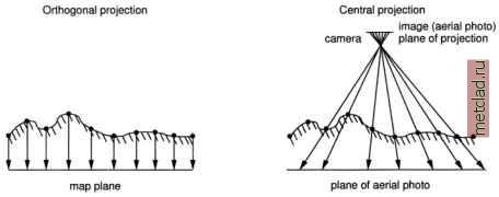 Figure 10.2. Terrain mapping to map plane (orthogonal projection) and aerial photo plane (central projection) (adapted from Albertz, 1991). Objects are displaced in the aerial photo (right) due to relief impact 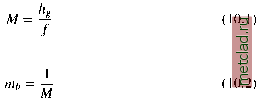 The height above ground [in meters] is a function of the topography, the terrain elevation above sea level has to be subtracted from the aircrafts recorded altitude above sea level. The focal length f of the camera is printed approximated (in millimeters) on the aerial photo, or, preferred, given correctly in the calibration certificate. The value must be changed to meters for the formula above. M is the image scale number. The image scalt which we are interested in can be derived from Equation 10.2. In general, higher terrain elevations within the aerial photo are recorded in larger scale than lower terrain elevations (Hildebrandt, 1996:152). Furthermore, the horizontal displacement depends on the elevation according to the central projection. Therefore, Equation 10.2 can be used to obtain only an averaged scale for the aerial photo. During ortho-rectification, the displacements are eliminated as the terrain undulation is taken into account. The image scale is usually not constant over the covered area: If the aircraft was horizontally tilted, then the image scale of the down-side (whose distance to ground is decreased) will be larger than the scale of the up-side. Undulated terrain adds further bias on the overall scale. If the terrain undulation covered by the aerial photo is relatively small it is possible to use an unrectified aerial photo for area or distance measurements. In such a case, minor distortions are ignored (Bierhals, 1988:91). The unrectified photo can be used, if the elevation range in this photo is less than 1/500 of the image scale number. For example, if an aerial photo was taken at a average scale of 1:10,000, the photo may be used unrectified if the elevation range does not exceed 20 m (10000/500=20). Otherwise, an orthophoto should be generated as described below. The earths curvature is another factor that affects aerial photos. It becomes a relevant factor only for high altitude or orbit-based images (such as for images from the Russian KVR1000 or similar systems). Note that also shrinking and stretching of film material may cause displacements as well as the usage of a non-photogrammetric scanner. Only if the report is unavailable, standard camera parameters may be taken from literature, if focal length or camera type are known (e.g. Hildebrandt, 1996:80). Aerial photos and map scale. The averaged image scale mi, (or the image scale number M) is elevation-dependent and can be calculated as follows: 10.2. FROM AERIAL PHOTO TO ORTHOPHOTO To generate an orthophoto we need a digital elevation model (DEM) and a topographic reference map. The elevation model is required to normalize the terrain undulation. The raster resolution of the DEM should be similar to the resolution of the aerial photo. Usually such high-resolution DEMs (raster cell length below 1 m) are not available. Therefore, interpolation of a given DEM to a higher resolution, as shown in Section 5.3.4 and Section 7.3.1, is recommended to minimize displacement effects. The topographic reference map is needed to find corresponding ground control points (GCPs) between aerial photo and this map for geocoding. The map scale of the reference map should at least match the average scale of the aerial photo (for example 1:5000), but should be probably larger to provide more details for improved geocod-ing accuracy. The ground control points are required to register the image xy coordinate system to a georeferenced coordinate system (like UTM or Gauss-Kruger). Metadata like time stamp, flight altitude above the sea level, tilt, and focal length will be taken from the calibration certificate and the annotation bar. An important requirement are the camera parameters. In general true orthophotos and pseudo orthophotos are distinguished. In true orthophotos all elevated objects such as building roofs are corrected for their displacement due to the central perspective. This means that displacement-corrected buildings are seen from above which leads to no-data areas where the displaced roofs have been hiding the ground (on the buildings back sides as seen from the nadir of the aerial photo). To create true orthophotos, you need an elevation model containing all individual building heights. High resolution DEMs can be produced from stereo measurements of the original aerial photo stereo pairs or from LIDAR flights which are done to create surface elevation models (compare Section 7.3.4). Generally, pseudo orthophotos are easier to generate since displacements of building roofs are not corrected. The tilted views of buildings and other structures of notable height remain unchanged so that the buildings sides remain partly visible. 10.3. ORTHOPHOTO GENERATION For accurate measurements, image mosaics and cross-referencing photos to other GIS data, it is necessary to generate orthophotos. The main features of an orthophoto are: compensation for the tilt of the aircraft;
|