
|
|
|
|
Главная --> Промиздат --> Map principle 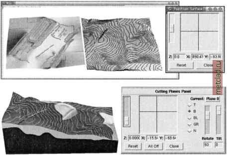 Figure 8.7. Viewing multiple surfaces next to each other or in their relative position with a cutting plane (elevation surface before and after construction) When working with multiple surfaces and cutting planes, keep in mind that in geoscience applications, the vertical spatial variability requires resolutions much higher than are the resolutions typically used in a horizontal plane. Therefore, a global vertical exaggeration ( zexag ) factor is applied for better visual perception of terrain. However, to visualize vertical relationships with sufficient detail, relative exaggeration of depths has to be used. For example, for multiple surfaces representing soil horizons, the depths need to be exaggerated relative to terrain surface (Brown et al., 1995). 8.2.3 Creating animations in 3D space (Ц) Animation is a powerful tool for exploring large data sets and for analyzing time series observations or modeling results. Fly-bys over digital elevation models or multiple surfaces can be created by using two types of key frame animations. Scripting with file sequence tool provides capabilities to build more complex animations with multiple map layers including combination of surfaces, vector data and sites. 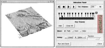 Figure 8.8. Fly-by animation menu in nviz Creating a fly-by. Animations simulating flying over a surface can be created using animation panels which allow you to define key frames, representing key positions defining your path and then render and save the surface views along this path. Basic control of the fly-by is provided by the menu Panel ~> Animation (see Figure 8.8). First, enter the number of images to be rendered as Tot. Frames . The default is 25, a larger number is suggested to get an interesting flight, for example, type in 100 followed by <ENTER>. Now select your initial viewing position using the viewing direction puck and perspective, height or twist sliders in the upper Controls panel. Click on Add to save this position. Then select the next position on the key frame (time) axis by dragging the thick vertical blue line to the right and define the second key (viewing) position by adjusting the direction, perspective, height or twist. Save your second key frame by clicking on Add . You can continue moving your viewing position and adding key frames until you reach the end of the time line. Additional frames will be automatically interpolated between the key frames as indicated by the black bars on the time axis. To avoid a jumpy flight, it is useful to start with a small number of key positions, for example, by locating four key frames after each 25% segment on the time axis. After defining the key positions and a number of key frames, run the coarse resolution movie by clicking on the play button (black right arrow) to get some feeling for how the controls work and see how fast and smoothly you are flying. If the flight is too fast, add more frames. You can also control the number of frames between the key positions by dragging the blue triangle on the Key Frames axis. To make the fly path smoother, activate the Spline button and control the sharpness of the curves on your path using the Tension slider. You can add vector and sites map layers to your surface by switching on the Show vect and Show site buttons. After previewing the animation by running the coarse resolution fly-by, you can render the full resolution images for your movie by selecting the Run and Save and providing a filename (e.g. film). Depending on the resolution, image size, and speed of your computer, the procedure may take some time. The result will be a series of image files, which are automatically numbered (e.g., film00000.ppm - film00099.ppm). The images are then used to create a movie file using external tools as described in the next paragraph. If you just want to try out animation, the simple animation tools described above are enough; however, for a serious animation work it is worth learning and using the Key frame animation panel which provides control over the frame rate and key frame time as well as refined control of the camera (viewing position and direction). The use of Key frame animation is described in detail in the Nviz tutorial. Converting series of images to movies. The rendered images are saved in the ppm, tiff or SGI/RGB format. To create an animation, you can merge them into an animation file using the scripts provided with the GRASS code or with external tools such as mpeg encode.5 To create an animated GIF using the rendered images film*.rgb at half their size run: rgb2gifanim -s 0.5 film.gif film*.rgb The MPEG movie can be created in a similar way using the script make.mpeg. These scripts use some image processing tools that may not be readily available, but you can create an animation by converting ppm images to gif with ppm2gif.sh and then merge them into a single animation file by gifmerge. You will find the scripts on the GRASS Tutorials Web site (see the Endnotes for reference). If you would like to have more control over the creation of the MPEG movie, you can use the MPEG encoding tools directly and define the movie in the parameter file mpegparam.txt, for example: OUTPUT my movie.mpg INPUT DIR . INPUT #### Put the number of significant digits in [ ] #### number has to be 5 including the wildcard #### (max. 99999 images): filmOOO*.rgb [00-99] END INPUT BASE FILE FORMAT PNM GOP SIZE 99 INPUT CONVERT sgitopnm * BSEARCH ALG CR0SS2 PSEARCH ALG LOGARITHMIC
|