
|
|
|
|
Главная --> Промиздат --> Map principle To define a new xy LOCATION, start grass53 and enter new names for LOCATION and MAPSET; for example, area-xy and userl. Similarly to the procedure described in Section 3.2 proceed to the question Please specify the coordinate system for location area-xy . The coordinate system we need here is A x,y . After entering a one line description, you reach the LOCATION region definition screen. Now define the region size in x and y direction (rows and columns). It should cover at least the size of the image or map that you want to import. The xy LOCATION can be defined larger than needed because the actual memory used depends only on the size of your imported file. When working with imagery data, set the west and south values to 0 (zero) and the north and east values to the number of rows and columns of the image (or more, compare Figure 3.7). The GRID RESOLUTION can be set to I, because the units are pixels. After leaving this menu and accepting the definition, the new LOCATION is created. You can return to the GRASS startup screen and leave it again to create the MAPSET and to enter GRASS. Later on, in Section 9.2.I, we describe a method for automatic creation of a LOCATION from a raster data set. 3.3. COORDINATE SYSTEM TRANSFORMATIONS Geospatial data for a given study area are often provided in different coordinate systems (for example, combination of the UTM, State Plane and geographic coordinates is quite common in USA). It is therefore important to have the capability to transform data between different projections and coordinate systems. 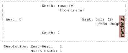 Figure 3.7. Definition of a region for xy LOCATION suitable for importing an image or scanned map. Units are pixels GRASS and its projection support through PROJ4. The projection library in GRASS 5.3 is either the PROJ 4.3.3 developed by USGS (Evenden, 1995) or any later PROJ4 version used as an external library. The PROJ4 library is now maintained by volunteers6 and contains a stand-alone program cs2cs for reprojection of coordinate lists. Use GRASS with a recent version of PROJ4 recommended, as it also supports datum transformations from version 4.4.5 onwards. The general procedure for transforming between two projections is (internally) always performed through geographical coordinates: Projection1 latitude-longitude -- Projection 2 The projection information in a GRASS LOCATION is stored in the PERMANENT MAPSET in files PROJ INFO and PROJ UNITS. The following parameters may appear depending on the actual projection: proj (projection type), name (projection name), ellps (ellipsoid), a (ellipsoid: equatorial radius), es (ellipsoid: eccentricity squared), zone (zone for the area), unfact (conversion factor from meters to other units, e.g. feet), lat 0 (standard parallel), lon 0 (central meridian), k (scale factor), x 0 (false easting) and y 0 (false northing). To simplify the definition of a projection, PROJ4 provides support for EPSG (European Petroleum Survey Group) codes, aimed at standardization of common projection definitions. Projections and coordinate systems including geodetic datum can either be constructed or selected via EPSG code from predefined list entries. The list of EPSG codes is usually installed at /usr/local/share/proj/epsg. Depending on the type of data that need to be transformed, transformations can be done in two ways: ASCII file coordinate lists can be transformed between any of the more than 120 supported projections by running the external command cs2cs provided by PROJ4; raster, vector and site map layers are transformed between two existing LOCATIONS with given coordinate systems using the commands r.proj, v.proj and s.proj. 3.3.1 Coordinates lists PROJ4 provides the command cs2cs for reprojection of point lists given by coordinate pairs; for example, resulting from GPS or for map corners. On command line, the source and the target projections have to be defined. Subsequently, the coordinate pairs are queried or read from an ASCII file, transformed, and written either to the screen or redirected to an output file. The program also reports the built-in projections (p, extended list with P), ellipsoids (e), prime meridians (m), datums (d) and units (u):  For example, to transform the comer points of the Spearfish LOCATION from UTM/Clark66/NAD27 to latitude-longitude/WGS84, we run (enter in one line): cs2cs -V +proj=utm +zone=13 +ellps=clrk66 +datum=NAD27 \ +units=m +to +proj=latlong This command prints out the projection parameters (due to the -v flag) and then waits for input. Now you can type in UTM coordinate pairs, optionally with the related elevation. Entering for example the north/west map corner of the Spearfish LOCATION delivers: which represents the corresponding latitude-longitude/WGS84 coordinates. The command cs2cs performs the required datum transformation. As other example, we transform coordinates from UTM/Clark66/NAD27 (Spearfish LOCATION) to LAEA/Sphere/no datum. We will store the values in a file. To get the LOCATION corner coordinates, start GRASS with the Spearfish LOCATION and run: From the reported values we create a file spearfishUTM NAD27.txt containing the following four corners. The input file must be written in plain ASCII format containing row-wise easting and northing: 589980 4928010 609000 4928010 609000 4913700 589980 4913700 Now we convert the coordinates in the file to the standard raster map projection of the National Atlas of the U.S.7, which is Lambert Azimuthal Equal Area (LAEA) on a Sphere: cat spearfishUTM NAD27.txt cs2cs -v +proj=utm +zone=13 \ +ellps=clrk66 +datum=NAD27 +units=m +to \ +proj=laea +lat 0=45 +lon 0=-100 +x 0=0 +y 0=0 +ellps=sphere\ +units=m > spearfishLAEA.txt
|