
|
|
|
|
Главная --> Промиздат --> Map principle map principle When working with GRASS, the projection and coordinate system must be defined when a new project (LOCATION in GRASS terminology) is defined. The map projection definition is stored in an internal file within the given LOCATION. It is used whenever the data need to be projected into a different projection or when calculations requiring information about the Earths curvature are performed. Different parameters are needed to define different projections and coordinate systems; therefore, it is important to understand the map projection terminology. 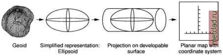 Figure 2.3. Earths surface representation in map projections and coordinate systems Shape of the Earth. Shape of the Earth is usually approximated by a mathematical model represented by an ellipsoid (also called a spheroid). A variety of cartographic ellipsoids have been designed to provide the best-fit properties for certain portions of the Earths surface, see for example Table 2.1. While the ellipsoid describes the shape of the Earth by a relatively simple mathematical function, the geoid, a physical approach to the description of the Earths shape, undulates responding to the distribution of the Earths mass which locally varies. The geoid is the equipotential surface of Earths gravity field and corresponds to the mean sea level. For map projections, the ellipsoids are usually sufficient for horizontal positioning; however, the geoid has to be used for exact elevation calculations. Geodetic or map datum. A set of constants specifying the coordinate system used for calculating the coordinates of points on Earth is called a geodetic datum. Horizontal datums define the origin and orientation of a coordinate system used to calculate the horizontal coordinates (usually northing and easting). Vertical datums define the coordinate system origin for calculating the elevation coordinate (mean sea level). For map layers to match, their coordinates must be computed using the same datum. Different datums mean a shift in the origin of the coordinate system, and that means a shift of the entire map. Map projection. To transform a curved Earth surface into a plane (flat sheet of paper or a computer screen), a map projection is used. Direct projection of a spherical object to a plane cannot be performed without distortion. The most common approach is to project the spheroid onto a developable surface, such as a cylinder or a cone which can be developed into a plane without deformation (tearing or stretching), see Figure 2.3. A large number of different projections have been designed with the aim to minimize the distortion and preserve certain properties. In general, the projections can be divided into three major groups (for a mathematical description refer to Bugayevskiy and Snyder, 2000:20-22): conformal, preserves angles (shapes for small areas), used for navigation and most national grid systems; equidistant, preserves certain relative distances, used for measurement of length; equivalent, preserves area, used for measurement of areas. Each of these properties (angle, distance, area) is preserved at the expense of the others. Because there is no perfect solution, the map projection is selected depending on the application. Most coordinate systems used for land surface mapping use conformal projections. The developable surfaces can either touch the spheroid (tangent case) or intersect it (secant case). Based on the geometry of the developable surface, the projections can be divided into: cylindrical, which transform the spherical surface to a tangent or secant cylinder; conic, which use the tangent or secant cone; azimuthal, which use a tangent or secant plane (flat sheet). The points or lines where a developable surface touches or intersects the spheroid are called standard points and standard lines with zero distortion (e.g. standard parallel for tangent cone or two standard parallels for secant cone). That means that the projected maps (or in the GIS the projected data) do not have uniform scale for the entire area, and the true map scale is preserved only along the standard lines. To minimize distortions, some projections reduce the scale along the standard parallel(s) or central meridian(s). This is expressed as a scalefactor smaller than 1.0 in the definition of such a projection. Transverse projections use developable surfaces rotated by 90° so that the standard (tangent) line is a meridian called central meridian instead of a standard parallel. Oblique projections may use any rotation defined by azimuth where azimuth is an angle between a maps central line of projection and the meridian it intersects, measured clockwise from north. Snyder, 1987, provides an excellent manual on map projections with map examples for many important projections. Coordinate system. To accurately identify a location on Earth, a coordinate system is required. It is defined by its origin (e.g. prime meridian, datum), coordinate axes (e.g. x, y, z), and units (angle: degree, gon, radiant; length: meter, feet).
|